

Introduction
This is the chapter web page to support the content in Chapter 11 of the book: Exploring Raspberry Pi – Interfacing to the Real World with Embedded Linux. The summary introduction to the chapter is as follows:
A key strength of Linux on embedded systems is the vast amount of software and device drivers that is freely available. Unfortunately, the overhead of running Linux is problematic for the performance of high-speed interfacing tasks—for example, generating or sampling bit patterns on general-purpose inputs/outputs (GPIOs) at high speeds. One solution to this problem is to use dedicated real-time slave processors and to communicate with them using high-level protocols. There are many suitable slave processors available, but this chapter is focused on just one platform: the Arduino. This chapter describes how the Raspberry Pi (RPi) can interface effectively to the Arduino using UART serial, I2C, and Serial Peripheral Interface (SPI) communication. Examples are provided of the Arduino in use as an input/output extender and as a dedicated high-speed slave processor.
After completing this chapter, you should hopefully be able to do the following:
- Interface the RPi to the Arduino using a UART serial connection to create a master/slave communications framework.
- Interface the RPi to the Arduino using the I2C bus and use a register-based framework to read and write values to/from the Arduino.
- Build high-speed, real-time interfacing application examples that utilize the I2C register-based framework.
- Use SPI to create a simple communications framework between the RPi and a slave Arduino.
- Program an Arduino using an RPi command-line interface.
Digital Media Resources
Below are some high-resolution images of the circuits described in the book. They are reproduced in colour and can be printed at high resolution to facilitate you in building the circuits.
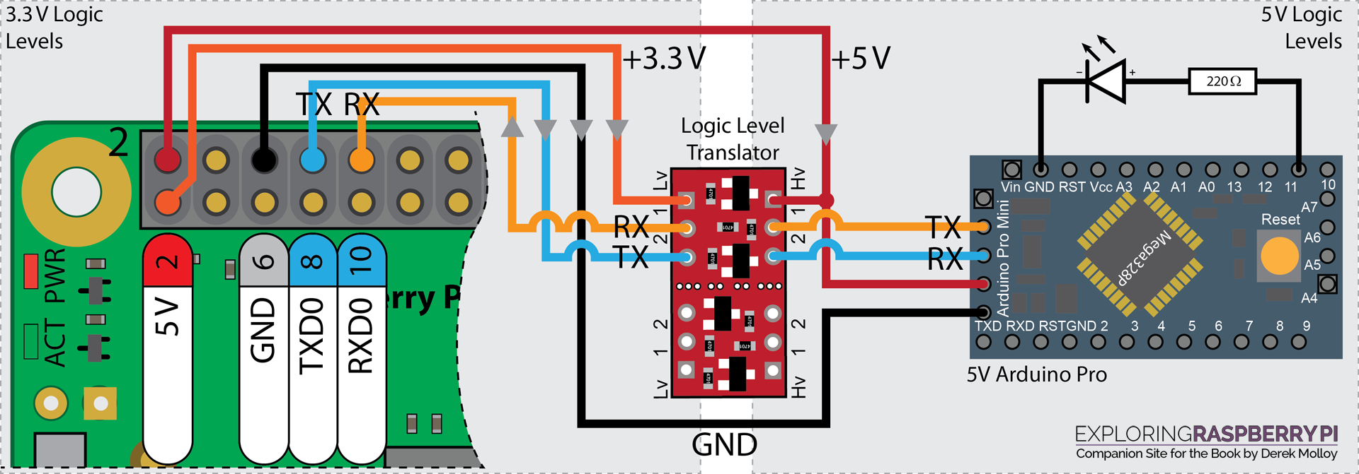
The Arduino UART Configuration
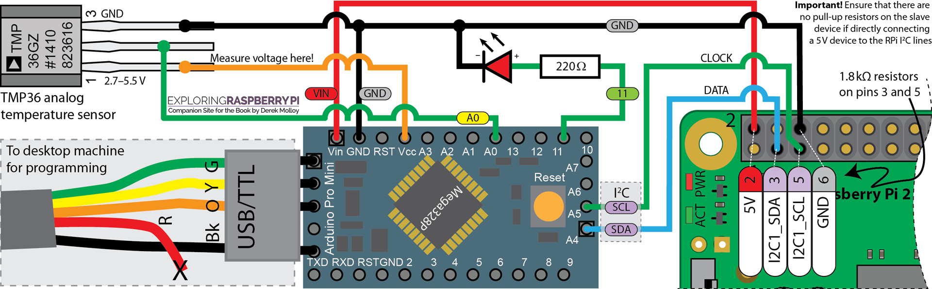
The Arduino I2C Configuration
My Arduino Video Series
An Introduction to the Arduino
This is a short introduction to the Arduino platform.
An Arduino on a Breadboard
This tutorial shows you how to build an Arduino on a breadboard. It describes the use of 16MHz and 20Mhz crystals for driving the Arduino and compares their use to the use of a resonator. A simple circuit is created that blinks an LED for 1000ms and 100ms. The Arduino is programmed on the breadboard using an Arduino shield’s Reset, TX and RX pins.
LCD Display Introduction
This short video looks at the different options available for connecting an LCD character display to an Arduino. It uses a wide set of displays: The nuelectronics display shield, 20×4, 20×2,16×2 and 8×2 display modules. It shows the code that you need to create an example display and describes the use of the POT in the display. The modules used are the nuelectronics display shield, JHD 204, WH1602, CM200200 and a YJ 802A.
Arduino Application – A Reaction Timer
In this video I combine three previous videos and write some code to create an Arduino based Reaction Timer. The entire circuit is built on a breadboard using an ATmega328P on its own, which is combined with a Newhaven Display LCD Module that has an RGB backlight. I work through the code in some detail and explain how to write the code for the reaction timer. At the end of the video I provide links to the previous videos that show how to build the three individual circuits: Breadboard PSU, Arduino on a Breadboard and Arduino LCD Tutorial.
8×8 LED Dot Matrix Display Tutorial
In this video a 2 Colour (red/green) 8×8 LED Dot Matrix Display circuit is developed that uses three 74HC595 ICs to drive the rows/columns and a darlington transistor array (UDN2981A) to source the current. An Arduino is used to provide the serial data and the source code is presented to show how this was achieved. The display is a common anode display and the experiment spends time examining the current constraints, explaining why we require transistor arrays to source or sink current.
Errata
None for the moment
Hello,
I was trying to complete the I2C echo test between an Arduino Nano and RPi, but when I run the i2cdump command I get a table of all XXs. The i2cdetect command displays the proper output though. Any help on what might be causing this issue would be much appreciated!
I ran into the exact same issue (i2cdetect sees Arduino, but i2cdump and i2cget fail when trying to read register values). After a few days driving myself nuts with various wiring configs and coding changes, it turned out to be the i2c driver on the Pi.
Specifically, the Pi was using the i2c_bcm2835 module. I switched to the i2c_bcm2708 module, and everything worked correctly. Here’s what I did:
sudo vi /etc/modules
Comment out “i2c_bcm2835” if it’s in there.
sudo vi /boot/config.txt
Add the following line:
dtoverlay=i2c-bcm2708
Then reboot the Pi and confirm it’s using i2c-bcm2708 (NOT i2c_bcm2835):
lsmod | grep i2c
The i2c echo test should work now.
As to WHY this is happening, that would require further investigation with a scope on the SDA and SCL lines to see what’s actually going across with the i2c_bcm2835 driver. Unfortunately I don’t have access to a scope at the moment.